Reading Workshop Drawings
Most projects within the online course include workshop drawings showing the dimensions, proportions and construction details needed to build each project.
These drawings are intentionally straightforward and are designed to be used alongside the video tutorials. No CAD experience is required and you are not expected to create drawings yourself.
Understanding Our Workshop Drawings
The workshop drawings used throughout the course are designed to communicate dimensions, proportions and construction details as clearly as possible.
Most projects are shown using a combination of:
- Front Elevation – looking directly at the front of the project
- Side Elevation – looking directly at one side
- Plan View – looking down from above
Together these views show the height, width, depth and layout of the project.
Example Workshop Drawing
The drawing below is taken from the Mitred Dovetailed Bookend project. It demonstrates the typical style of workshop drawing used throughout the course.
- Front elevation showing overall height and width
- Side elevation showing depth and construction details
- Plan view showing the layout from above
- Dimensions shown directly in millimetres
- Important construction details clearly identified where required
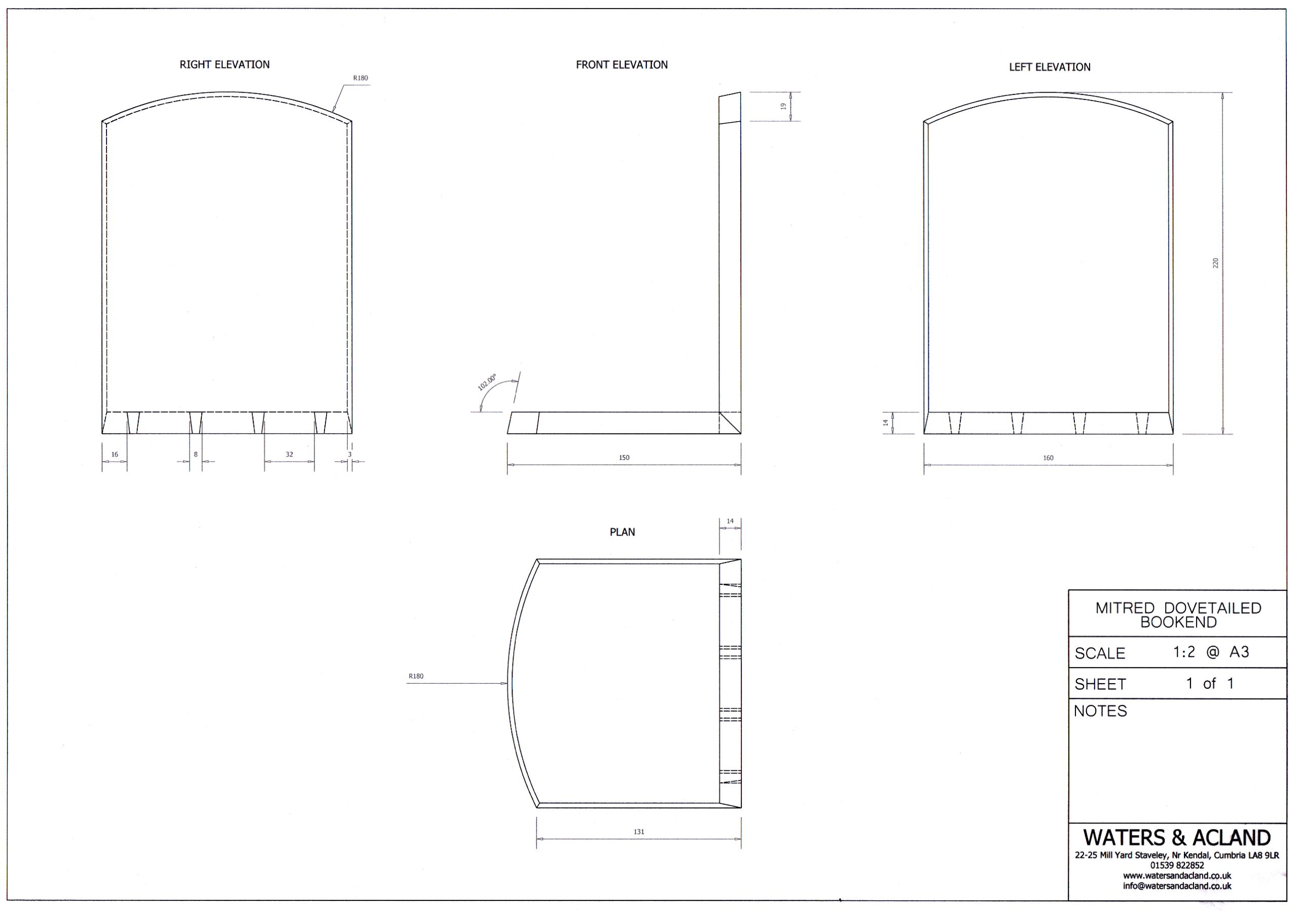
Click or tap the image to view it full size.
Understanding The Views
Front Elevation
Usually shows the overall width and height of the piece, together with visible construction details such as rails, stiles, doors, drawers and panels.
Side Elevation
Shows the depth of the piece and often clarifies details that are not visible from the front.
Plan View
Looking directly down from above. This view is commonly used to show widths, spacing and component locations.
Reading Dimensions
Dimensions throughout the course are generally shown in millimetres (mm).
Drawings normally include:
- Overall height
- Overall width
- Overall depth
- Component thicknesses where required
- Locations of joinery or important features
Component Dimensions
Drawings often include dimensions for individual components or a cutting list. These dimensions refer to the finished size of the part.
In practice, most furniture makers prepare stock slightly oversized before bringing components to their final dimensions during the build.
Joinery Information
Workshop drawings are intended to communicate the size and position of components and joinery rather than provide step-by-step construction instructions.
The accompanying video tutorials demonstrate the methods, techniques and sequence used to build each project.
The drawings and videos should therefore be used together throughout the build.
Do I Need CAD Experience?
No.
The course does not require any CAD software knowledge and you are not expected to create technical drawings.
The drawings simply provide a clear and efficient way of communicating dimensions, proportions and construction details.
Using Drawings Alongside The Tutorials
Most students find it helpful to watch a section of the tutorial first and then refer to the drawing when preparing components and checking dimensions.
This mirrors professional furniture making practice, where drawings and practical instruction are used together throughout a project.
Adapting Dimensions To Suit Your Timber
Project dimensions shown in the drawings are intended as guides rather than fixed requirements. Adapting projects to suit available timber sizes, tooling and personal preferences is encouraged and forms part of the learning process.
For example, if a project is shown using 20mm square stock but your local supplier only stocks 25mm square material, it is often perfectly reasonable to adjust the design accordingly.
When making changes, remember that altering one dimension may affect others elsewhere in the drawing. Component lengths, joinery positions, clearances and overall proportions may all need to be reviewed to ensure the project still works as intended.
A Note On Project Drawings
The workshop drawings are intended to support the tutorials rather than replace them.
While dimensions and construction details are shown on the drawings, the accompanying video tutorials demonstrate the techniques, order of operations and practical considerations involved in building each project.
Most members find it useful to keep the drawing open or printed while working through the videos.